Supplementary Uplink

Introduction

In 5G NR, a downlink carrier may be associated with two uplink carriers (the non-SUL carrier and the SUL carrier), where the Supplementary Uplink (SUL) carrier is typically located in lower frequency bands, thereby providing enhanced uplink coverage.

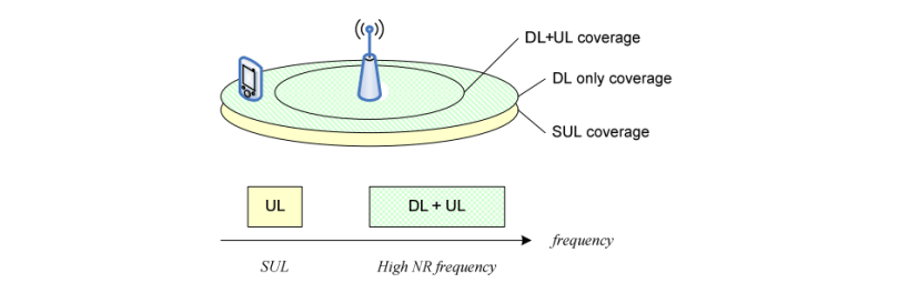
Example of Supplementary Uplink: With SUL, the UE is configured with 2 ULs for one DL of the same cell as depicted in figure below:

Example of Supplementary Uplink

Below are the Operating Bands defined by 3GPP for NR in Frequency Range 1 where the duplex mode is SUL:

Operating Bands supporting SUL as duplex mode

Supplementary Uplink (in detail)

In conjunction with a UL/DL carrier pair (FDD band) or a bidirectional carrier (TDD band), a UE may be configured with additional, Supplementary Uplink (SUL) which can improve UL coverage for high frequency scenarios.

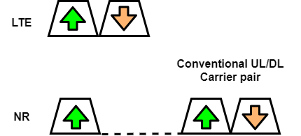
Since the lower frequency bands are already occupied by LTE primarily, so for enabling early NR deployment in lower-frequency spectra, LTE/NR spectrum co-existence is thought of as the way for an operator to deploy NR in the same spectrum as an already existing LTE deployment. Two co-existence scenarios were identified in 3GPP and guided the NR design:

  1. LTE/NR co-existence in both DL and UL directions
  2. There is co-existence only in the UL direction, typically within the UL part of a lower-frequency paired spectrum, with NR downlink transmission taking place in the spectrum dedicated to NR, typically at higher frequencies. NR supports a supplementary uplink (SUL) to specifically handle this scenario.

SUL implies that a conventional downlink/ uplink (DL/UL) carrier pair has an associated or supplementary uplink carrier with the SUL carrier typically operating in lower-frequency bands. As an example, a downlink/uplink carrier pair operating in the 3.5 GHz band could be complemented with a supplementary uplink carrier in the 800 MHz band.

In SUL scenario, the non-SUL uplink carrier is typically significantly more wideband compared to the SUL carrier. Thus, under good channel conditions such as the device located relatively close to the cell site, the non-SUL carrier typically allows for substantially higher data rates compared to the SUL carrier. At the same time, under bad channel conditions, for example, at the cell edge, a lower-frequency SUL carrier typically allows for significantly higher data rates compared to the non-SUL carrier, due to the assumed lower path loss at lower frequencies.

In case of Supplementary Uplink, the UE is configured with 2 UL carriers for one DL carrier of the same cell, and uplink transmissions on those two UL carriers are controlled by the network to avoid overlapping PUSCH/PUCCH transmissions in time. Overlapping transmissions on PUSCH are avoided through scheduling while overlapping transmissions on PUCCH are avoided through configuration (PUCCH can only be configured for only one of the 2 ULs of the cell). In addition, initial access is supported in each of the uplink

Note:

  1. In paired spectrum, DL and UL can switch BWP independently. In unpaired spectrum, DL and UL switch BWP simultaneously. Switching between configured BWPs happens by means of RRC signaling, DCI, inactivity timer or upon initiation of random access. When an inactivity timer is configured for a serving cell, the expiry of the inactivity timer associated to that cell switches the active BWP to a default BWP configured by the network. There can be at most one active BWP per cell, except when the serving cell is configured with SUL, in which case there can be at most one on each UL carrier.
  2. When SUL is configured, a configured uplink grant can only be signaled for one of the 2 ULs of the cell
  3. SUL differs from the aggregated uplink in that the UE may be scheduled to transmit either on the supplementary uplink or on the uplink of the carrier being supplemented, but not on both at the same time.

Random Access in case of Supplementary Uplink (SUL)

For random access in a cell configured with SUL, the network can explicitly signal which carrier to use (UL or SUL). Otherwise, the UE selects the SUL carrier if and only if the measured quality of the DL is lower than a broadcast threshold. Once started, all uplink transmissions of the random-access procedure remain on the selected carrier.

SIB1 ::= SEQUENCE {

    servingCellConfigCommon  ServingCellConfigCommonSIB    OPTIONAL,   — Need R

}

ServingCellConfigCommonSIB ::= SEQUENCE {

    supplementaryUplink  UplinkConfigCommonSIB   OPTIONAL,   — Need R

}

Supplementary Uplink related configuration is present as a part of SIB1. Before initially accessing a cell, a device will thus know if the cell to be accessed is SUL cell or not. If the cell is SUL cell and the device supports SUL operation for the given band combination, initial random access may be carried out using either the SUL carrier or the non-SUL uplink carrier. The cell system information provides separate RACH configurations for the SUL carrier and the non-SUL carrier and a device capable of SUL determines what carrier to use for the random access by comparing the measured RSRP of the selected SS block with a carrier-selection threshold also provided as part of the cell system information.

  • If the RSRP is above the threshold, random access is carried out on the non- SUL carrier.
  • If the RSRP is below the threshold, random access is carried out on the SUL carrier.

In practice, the SUL carrier is thus selected by devices with a (downlink) pathloss to the cell that is larger than a certain value. The device carrying out a random-access transmission will transmit the random-access message 3 on the same carrier as used for the preamble transmission.

For other scenarios, when a device may do a random access, that is, for devices in connected mode, the device can be explicitly configured to use either the SUL carrier or the non-SUL carrier for the uplink random-access transmissions.

Control Signaling in case of Supplementary Uplink (SUL)

In the case of supplementary uplink operation, a device is explicitly configured (by means of RRC signaling) to transmit PUCCH on either the SUL carrier or on the conventional (non-SUL) carrier.

In terms of PUSCH transmission, the device can be configured to transmit PUSCH on the same carrier as PUCCH. Alternatively, a device configured for SUL operation can be configured for dynamic selection between the SUL carrier or the non-SUL carrier. In the latter case, the uplink scheduling grant will include SUL/non-SUL indicator that indicates on what carrier the scheduled PUSCH transmission should be carried. Thus, in the case of supplementary uplink, a device will never transmit PUSCH simultaneously on both the SUL carrier and on the non-SUL carrier.

If a device is to transmit UCI on PUCCH during a time interval that overlaps with a scheduled PUSCH transmission on the same carrier, the device instead multiplexes the UCI onto PUSCH. The same rule is true for the SUL scenario, that is, there is not simultaneous PUSCH and PUCCH transmission even on different carriers. Rather, if a device is to transmit UCI on PUCCH one carrier (SUL or non-SUL) during a time interval that overlaps with a scheduled PUSCH transmission on either carrier (SUL or non-SUL), the device instead multiplexes the UCI onto the PUSCH.

SUL Carrier Co-Existence with LTE UL Carrier leading to enhanced User Experience

As mentioned above, One SUL scenario is when the SUL carrier is located in the uplink part of paired spectrum already used by LTE. In other words, the SUL carrier exists in an LTE/NR uplink coexistence scenario. In many LTE deployments, the uplink traffic is significantly less than the corresponding downlink traffic. Consequently, in many deployments, the uplink part of paired spectra is not fully utilized. Deploying an NR supplementary uplink carrier on top of the LTE uplink carrier in such a spectrum is a way to enhance the NR user experience with limited impact on the LTE network.

SUL carrier coexisting with LTE Uplink Carrier

Reduction in Latency

In the case of TDD, the separation of uplink and downlink in the time domain may impose restrictions on when uplink data can be transmitted. By combining the TDD carrier with a supplementary carrier in paired spectra, latency-critical data can be transmitted on the supplementary uplink immediately without being restricted by the uplink-downlink partitioning on the normal carrier.

Difference between Carrier Aggregation (CA) and supplementary uplink (SUL)

In a typical carrier aggregation scenario:

  • Main aim of carrier aggregation is to enable higher peak data rates by increasing the bandwidth available for transmission to/from a device.
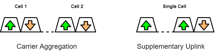
  • The two (or more) carriers are often of similar bandwidth and operating at similar carrier frequencies, making aggregation of the throughput of the two carriers more beneficial. Each uplink carrier is operating with its own associated downlink carrier, simplifying the support for simultaneous scheduling of multiple uplink transmissions in parallel. Formally, each such downlink carrier corresponds to a cell of its own and thus different uplink carriers in a carrier-aggregation scenario correspond to different cells.

While in case of SUL scenario:

  • Main aim of SUL is to extend uplink coverage, that is, to provide higher uplink data rates in power-limited situations, by utilizing the lower path loss at lower frequencies
  • The supplementary uplink carrier does not have an associated downlink carrier of its own. Rather, the supplementary carrier and the conventional uplink carrier share the same downlink carrier. Consequently, the supplementary uplink carrier does not correspond to a cell of its own. Instead, in the SUL scenario there is a single cell with one downlink carrier and two uplink carriers.
Carrier Aggregation vs Supplementary Uplink

Is there something possible like Supplementary Downlink also?

Yes, since the carrier aggregation framework allows for the number of downlink carriers to be larger than the number of uplink carriers, some of the downlink carriers can be thought of as supplementary downlinks. One common scenario is to deploy an additional downlink carrier in unpaired spectra and aggregate it with a carrier in paired spectra to increase capacity and data rates. No additional mechanisms beyond carrier aggregation are needed and hence the term supplementary downlink is mainly used from a spectrum point of view.

Is it possible to have combination of SUL Carrier and Carrier Aggregation?

In principle, it is possible to have a combination of SUL carrier and carrier aggregation, for example, a situation with carrier aggregation between two cells (two DL/UL carrier pairs) where one of the cells is SUL cell with an additional supplementary uplink carrier. However, currently there are no band combinations defined for such carrier-aggregation/SUL combinations

References:

  1. 3GPP TS 38.300 version 15.9.0 Release 15
  2. www.sharetechnote.com
  3. “5G NR – The next generation wireless access technology” – By Erik Dahlman, Stefan Parkvall, Johan Sköld

Introduction to Numerology

Introduction

Numerology corresponds to one subcarrier spacing in the frequency domain. NR supports a flexible numerology with a range of subcarrier spacings, based on scaling a baseline subcarrier spacing of 15 kHz. By scaling a reference subcarrier spacing by an integer N, different numerologies can be defined.

Need for Multiple Numerologies

  1. In order to support the wide range of deployment scenarios, from large cells with sub-1 GHz carrier frequency up to mm-wave deployments with very wide spectrum allocations, NR supports a flexible OFDM numerology with subcarrier spacings ranging from 15 kHz up to 240 kHz with a proportional change in cyclic prefix duration.
  2. Also, having a single numerology for all scenarios is not efficient and probably not possible at all.

These were the primary motives to have multiple numerologies

For the lower range of carrier frequencies, from below 1 GHz up to a few GHz, the cell sizes can be relatively large and a cyclic prefix capable of handling the delay spread expected in these type of deployments, a couple of microseconds, is necessary. Consequently, a subcarrier spacing in the LTE range or somewhat higher, in the range of 15-30 kHz, was needed.

For higher carrier frequencies approaching the mm-wave range, implementation limitations such as phase noise become more critical, calling for higher subcarrier spacings. At the same time, the expected cell sizes are smaller at higher frequencies because of the more challenging propagation conditions. The extensive use of beamforming at high frequencies also helps reduce the expected delay spread. Hence, for these types of deployments a higher subcarrier spacing, and a shorter cyclic prefix are suitable.

Different Numerologies

The numerology is based on exponentially scalable sub-carrier spacing Δf = 2µ × 15 kHz with µ = {0,1,3,4} for PSS, SSS and PBCH and µ = {0,1,2,3} for other channels. Normal CP is supported for all sub-carrier spacings, Extended CP is supported for µ=2 (60kHz). 12 consecutive sub-carriers form a Physical Resource Block (PRB). Up to 275 PRBs are supported on a carrier.

With the increase in numerology, the number of slots increase within the subframe, leading to increase in the number of symbols sent in a given time. So effectively, an OFDM symbol is shortened by half in the next higher numerology. Scaling by powers of two is beneficial as it maintains the symbol boundaries across numerologies, which simplifies mixing different numerologies on the same carrier.

Supported Transmission Numerologies

Reference: 3GPP TS 38.300 version 15.9.0 Release 15 (https://www.etsi.org/deliver/etsi_ts/138300_138399/138300/15.09.00_60/ts_138300v150900p.pdf)

15 kHz subcarrier spacing was selected as the baseline for NR. From the baseline subcarrier spacing, subcarrier spacings ranging from 15 kHz up to 240 kHz with a proportional change in cyclic prefix duration as shown in Table below are derived. Note that 240 kHz is supported for the SS block only and not for regular data transmission.

Subcarrier spacings supported by NR

NR time domain structure consist of 10ms radio frame divided into 10 subframes each of 1ms. A subframe is in turn divided into slots consisting of 14 OFDM symbols each, which means that the duration of the slot in milliseconds is dependent on the numerology. For the 15 kHz subcarrier spacing, an NR slot has a structure that is identical to the structure of an LTE subframe, which is deliberately kept like this considering coexistence of LTE with NR.

Below figure shows the frame, subframe and slot structure for different numerologies:

Frame, Subframe and Slot Structure for different numerologies

As shown above, the capacity is same between all carrier spacings if the bits/Hz is used as a unit. The carrier spacing is increased but the number of symbols per time unit increases with the higher numerology. Above figure just tries to show this for 15 and 30 kHz subcarrier spacing. The number of subcarriers is reduced by half but the number of slots per symbol per time unit is doubled.

Advantages of Numerology:

  • One of the services in 5G is URLLC, ultra reliable low latency communication and the objective is to have a latency of less than 1ms, which means that scheduling interval must be reduced below 1ms for these types of services. Fortunately, with the support of different numerologies, it is rather simple to reduce the time as the slot time is decreased with higher numerology. This functionality is used to support flexible TTI (Transmission Time Interval), which gives scheduler in base station, a chance to decide how often it will be taking scheduling decision. Figure below, shows how TTI can be scaled with numerology, but as the URLLC service is scheduled for release 16, the numbers should be seen as examples of possible TTI values.
Flexible TTI
Flexible TTI
  • In 5G NR, UE can be configured to only monitor a part of total transmission bandwidth called Bandwidth Part (BWP). There were 2 major reasons behind using BWP instead of whole bandwidth:
    • The wide transmission bandwidth used in some cases might cause the UE to consume too much power from battery.
    • There may also be some UE categories that cannot receive the full bandwidth due to reduced complexity (machine type communication) in order to reduce the cost of the device.

But in 5G NR, the UE can be configured with up to 4 BWPs where only one can be active at a time in the 1st release. Different BWPs can be of different numerologies, which can be used to reduce the latency for certain services. If a device is capable of simultaneous reception of multiple bandwidths parts, it is in principle possible to, on a single carrier, mix transmissions of different numerologies for a single device, although release 15 only supports a single active bandwidth part at a time.

In the downlink, a device is not assumed to be able to receive downlink data transmissions, more specifically the PDCCH or PDSCH, outside the active bandwidth part. The numerology of the PDCCH and PDSCH are restricted to the numerology configured for the bandwidth part. So, in release 15, a device can only receive one numerology at a time as multiple bandwidth parts cannot be simultaneously active. A device is not expected to monitor downlink control channels while doing measurements outside the active bandwidth part.  In the uplink, a device transmits PUSCH and PUCCH in the active uplink bandwidth part only.

  • Since a slot is defined as a fixed number of OFDM symbols, a higher subcarrier spacing (At higher carrier frequency) leads to a shorter slot duration which could be used to support lower-latency transmission, but since the cyclic prefix also shrinks when increasing the subcarrier spacing, it is not a feasible approach in all deployments. Therefore, NR supports a more efficient approach to low latency by allowing for transmission over a fraction of a slot, sometimes referred to as “mini-slot” transmission. Such transmissions can also preempt an already ongoing slot-based transmission to another device, allowing for immediate transmission of data requiring very low latency.
  • NR will also have the capability to operate with mixed numerology on the same RF carrier and will have an even higher flexibility than LTE in terms of frequency domain scheduling and multiplexing of devices within a base station RF carrier.

Disadvantage of Numerology:

  • The flexibility provided by multi-numerology system comes at the cost of additional interference, known as inter-numerology interference (INI). Apart from causing the loss of orthogonality among subcarriers of different numerologies in frequency domain, mixed numerologies also cause difficulty in achieving symbol alignment in time domain. With the same sampling rate, an OFDM symbol of one numerology does not perfectly align with the symbol of another numerology, which makes synchronization within the frame difficult. Researches are ongoing to minimize the effect of INI.

Reference: https://ieeexplore.ieee.org/abstract/document/8861343

30 Important differences between 5G NR and LTE

This is my 1st blog where i will be sharing some basic differences between 5G NR and LTE. There can be multiple other differences also but these are some of the selected ones, which i wanted to share with everyone. I might add few more later. Also, i will try to elaborate more about individual difference with images and figures in my subsequent blogs, where i will be elaborating more about individual topics.

I hope that i have assembled good enough differences for basic understanding, including some protocol level differences too. Please go ahead, read them and do share your review comments or suggestions.

Happy reading !!

Always – on signal support

LTE (Long Term Evolution): was designed to support always on signals be it any condition or situation, leading to a lot of wastage of resources and required continuous evaluation. For Example: System information broadcast, signals for detection of base station, reference signals for channel estimation etc.

NR (New Radio): Always-on transmissions are minimized in order to enable higher network energy performance and higher achievable data rates, causing reduced interference to other cells.

Assigned spectrum

LTE: Just introduced support for licensed spectra at 3.5 GHz and unlicensed spectra at 5 GHz.

NR: It’s first release supports licensed-spectrum operation from below 1 GHz up to 52.6 GHz and planning is ongoing for extension to unlicensed spectra.

Flexibility support for time/frequency resources

LTE: has majorly supported fix timing/frequency for transmission in certain situations. For Ex: Uplink Synchronous HARQ protocol, where a retransmission occurs at a fixed point in time after the initial transmission.

NR: believes in configurable time/frequency resources. It avoids having transmission on fixed resources.

Channel estimation

LTE: dependent on cell-specific reference signals for channel estimation, which are always transmitted.

NR: For channel estimation, NR doesn’t include cell-specific reference signals, instead relies on user specific demodulation reference signals, which are not transmitted unless there is data to transmit, thereby improving energy performance of the network.

Dynamic uplink downlink allocation

LTE: Uplink and downlink allocation does not change over time. Even though a later feature called eIMTA allowed some dynamics in UL DL allocation.

NR: Supports dynamic TDD, which means dynamic assignment and reassignment of time domain resources between UL and DL directions.

Device and Network Processing time

LTE: Better than 3G but not enough considering future requirements under highly dense environment for certain applications

NR: Processing times are much shorter in NR for both device and network. For Example: A device must respond with an HARQ ACK within a slot or even lesser (depending on device capabilities) after receiving a downlink data transmission.

Low Latency Support

LTE: Requires MAC and RLC layers to know the amount to data to transmit before any processing takes place, which makes it difficult to support very low latency.

NR: This is one of the most important characteristics of NR. Let me explain this support by giving 2 examples below:

  1. Header structures in MAC and RLC have been chosen to enable processing without knowing the amount of data to transmit, which is especially important in the UL direction as the device may only have a few OFDM symbols after receiving the UL grant until the transmission should take place.
  2. By locating the reference signals and downlink control signaling carrying scheduling information at the beginning of transmission and not using time domain interleaving across OFDM symbols, a device can start processing the received data immediately without prior buffering, thereby minimizing the decoding delay.

Error Correcting Codes

LTE: uses Turbo coding for data, which are the best solution at the lower code rate (For example: 1/6, 1/3, 1/2)

NR: uses LDPC (Low density Parity check) coding in order to support higher data rate as it offers lower complexity at higher coding rates as compared to LTE. They perform better at higher code rates (For Example: 3/4, 5/6, 7/8)

Time Frequency Structure of Downlink control channels

LTE: Less flexible as it needs full carrier bandwidth

NR: Has more flexible time frequency structure of downlink control channels where PDCCH’s are transmitted in one or more control resource sets (CORESETS) which can be configured to occupy only part of the carrier bandwidth.

Service Data Application Protocol layer

LTE: Not present

NR: Introduced to handle new Quality of service requirements when connecting to 5G core network. SDAP is responsible for mapping QoS bearers to radio bearers according to their quality-of-service requirements.

RRC States

LTE: Supported only 2 states: Idle and Connected

NR: Supports a 3rd state also called the RRC_INACTIVE, which is introduced to reduce the signaling load and the associated delay in moving from idle-to-active transition. In this state, RRC context is kept in both the device and the gNB.

In Sequence Delivery of RLC Packets

LTE: Supports reordering and in sequence delivery of RLC PDUs to higher protocol layers, leading to more delays.

NR: doesn’t support in-sequence delivery of RLC PDUs in order to reduce the associated delay incurred by the reordering mechanism which might be unfavorable for services that require very low latency. By doing this, RLC reduces the overall latency as packets do not have to wait for retransmission of an earlier missing packet before it is delivered to higher layers but can be forwarded immediately.

Concatenation of RLC PDUs

LTE: supported it to disallow RLC PDUs to be assembled in advance

NR: Removed this from RLC protocol to support assembly of RLC PDUs in advance, prior to receiving the Uplink Scheduling Grant.

Location of MAC Header

LTE: All the MAC Headers corresponding to certain RLC PDUs are present in the beginning of the MAC PDU.

NR: MAC Headers are distributed across the MAC PDU such that the MAC header related to a certain RLC PDU is located immediately next to RLC PDU, which is motivated by efficient low latency processing. With the structure in NR, MAC PDU can be assembled “on the fly” since there is no need to assemble the full MAC PDU before the header fields can be computed, leading to reduction in processing time and hence the overall latency.

HARQ Retransmission Unit

LTE: sends whole transport block in case of retransmission even if there is issue in only a small part of the transport block, which is very inefficient.

NR: supports HARQ retransmissions at a much finer granularity called code-block group, where only a small part of big transport block needs to be retransmitted.

Number of HARQ processes

LTE: Max supported was 8 for FDD and up to 15 processes for TDD, depending on the UL- DL configuration.

NR: Max supported is 16

HARQ in Uplink

LTE: It was synchronous HARQ as the timing of retransmission was fixed depending on the max number of HARQ Processes. There was no associated HARQ process number as in Downlink HARQ.

NR: It is asynchronous HARQ in both UL and DL as gNB explicitly signals the HARQ process number to be used by the UE, as part of the downlink control information. It was required to support dynamic TDD where there is no fixed UL/DL allocation.

Initial Access

LTE: Used a concept of two synchronization signals (PSS & SSS) with a fixed format which enabled UEs to find a cell.

NR: Uses a concept of Synchronization signal block (SSB), spanning 20 resource blocks and consisting of PSS, SSS & PBCH. The timing of the SSB block can be set by network operator.

Location of synchronization signals

LTE: Located in the center of transmission bandwidth and are transmitted once every 5ms.

NR: Signals are not fixed but located in a synchronization raster. When found, UE is informed on where in the frequency domain it is located. SS Block by default is transmitted once every 20ms but can be configured to be between 5 and 160ms.

Beam Forming of Synchronization signals

LTE: Not supported

NR: Supported

Beam forming of Control channels

LTE: Not supported

NR: supported and requires a different reference signal design with each control channel having its own dedicated reference signal.

Cyclic prefix

LTE: 2 different cyclic prefixes are defined, normal and extended where extended cyclic prefix was only used for specific environments with excessive delay spread, where performance was limited by time dispersion.

NR: Defines a normal cyclic prefix only, with an exception of 60 kHz subcarrier spacing where both are defined.

Subframe & Slot

LTE: with its single subcarrier spacing, number of slots in a subframe are always fixed. A frame is made up of 10 subframes each of 1ms, making the frame duration of 10ms. Each subframe carries 2 slots, so 20 slots makes a complete frame.

NR: Subframe is a numerology independent time reference while a slot is the typical dynamic scheduling unit. NR slot has the same structure as an LTE subframe with normal cyclic prefix for 15kHz subcarrier spacing, which is beneficial from a co-existence perspective.

Frame Structure

LTE: 2 frames structures were used in LTE which were later expanded to three for supporting unlicensed spectra.

NR: Single frame structure can be used to operate in paired as well as unpaired spectra.

Resource Block

LTE: Uses two-dimensional resource blocks of 12 subcarriers in the frequency domain and 1 slot in the time domain, so transmission occupied 1 complete slot (at least in the original release)

NR: NR resource block is a one-dimensional entity spanning the frequency domain only, reason being the flexibility in time duration for different transmissions. NR supports multiple numerologies on the same carrier, so there are multiple resource sets of resource grids, one for each numerology.

DC subcarrier

LTE: For downlink signals, the DC subcarrier is not transmitted, but is counted in the number of subcarriers. For uplink, the DC subcarrier does not exist because the entire spectrum is shifted down in frequency by half the subcarrier spacing and is symmetric about DC. This is the subcarrier in the OFDM/OFDMA signal whose frequency would be equal to the RF Center frequency of the station. Generally, all devices have the DC coinciding with the center frequency.

NR: DC subcarrier is used as NR devices may not be centered around the carrier frequency. Each NR device may have its DC located at different locations in the carrier.

Max Supported Bandwidth

LTE: Maximum carrier bandwidth of 20 MHz

NR: designed to support very high bandwidths, up to 400 MHz for a single carrier.

Carrier Spacing

LTE: There was fixed carrier spacing of 15kHz.

NR: Concept of numerology is created, keeping the base value of carrier spacing as 15 KHZ. Along with 15kHz, other supported values are 30, 60, 120 and 240 kHz to cater to different needs in different scenarios.

Massive MIMO

LTE: used normal MIMO and the maximum number of antennas in MIMO is 8 (DL) * 8(UL) using spatial multiplexing by UE Category 8

NR: Uses the concept of MIMO with an antenna array system using massive number of antennas, which can go up to 256(DL) * 32(UL).

Key Performance Indicators along with other differences:

LTE:

  • Peak Data Rate (With LTE-A): Downlink (1 Gbits/s), Uplink (.5 Gbits/s)
  • Peak Spectral Efficiency: Downlink (30 bps/Hz) – with 8-layer spatial multiplexing, Uplink (15 bps/Hz) – with 4-layer spatial multiplexing
  • Control Plane Latency: <100ms
  • User Plane Latency: <10ms
  • Mobility (With LTE-A): Device speeds up to 500 Km/h
  • Max Supported Bandwidth: 20 MHz
  • Waveform: CP-OFDM for DL, SC-FDMA for UL
  • Maximum number of subcarriers: 1200
  • Slot-Length: 7 symbols in 500us

NR:

  • Peak Data Rate: Downlink (20 Gbits/s), Uplink (10 Gbits/s)
  • Peak Spectral Efficiency: Downlink (30 bps/Hz), Uplink (15 bps/Hz)
  • Control Plane Latency: <10ms
  • User Plane Latency: <0.2ms for URLLC
  • Mobility: Device speeds up to 500 Km/h
  • Max Supported Bandwidth: 100 MHz in Frequency Range1 (400 MHz to 6 GHz) and up to 400 MHz in Frequency Range2(24.25 GHz to 52.6 GHz)
  • Waveform: CP-OFDM for DL, CP-OFDM and DFT-s-OFDM for UL
  • Maximum number of subcarriers: 3300
  • Slot-Length: 14 symbols (duration depends on subcarrier spacing), 2,4 and 7 symbols for mini-slot

Below is the you tube link of a very basic and interesting 5G NR Webinar from a 5G expert from Ericsson (Mr. Erik Dahlman), one of the authors of the Book “5G NR _ the next generation wireless access technology”. Happy Learning!

  1. great post with clear concept. thanks