
What is MIMO
MIMO (Multiple Input Multiple Output) antenna technology is a way of increasing the capacity of a radio link using multiple transmit antennas and multiple receive antennas. Due to multipath propagation and decorrelated paths between the transmitter and receiver, multiple data streams can be sent over the same radio channel, thus increasing the peak data rate per user along with the capacity of the cellular network. MIMO has been part of LTE since the 1st release. LTE started with a 2×2 MIMO which means 2 transmit antennas at the base station (BS) side and 2 receive antennas at the UE side. LTE allow applications of up to 8 spatial layers in DL direction and up to 4 spatial layers in UL direction. Commercial LTE networks tend to use 2 or 4 spatial layers.
MIMO can be implemented in many ways:
- Diversity: Multiple transmit and receive antennas are used to increase coverage (increased signal to interference plus noise ratio, SINR). Transmit diversity means to have multiple antennas at the sending side and receive diversity means to have multiple antennas at the receiver side to increase the captured radio energy.
- Spatial Multiplexing: When multiple antennas are used by both sender and receiver, multiple streams can be sent with different information for increased user data bit rate. Transmission of data uses several layers with small phase shift between the layers, enabling a receiver to decode the layers separately.
- Beamforming (BF): Multiple transmit antennas will direct the radio energy in a narrow sector to increase the SINR and thereby increasing the coverage (or increase the bitrate to the UE at a certain distance from the BS).
If different data streams are sent to the same receiver, it is referred to as Single User MIMO (SU-MIMO), while if the data streams are transmitted to different users, it is referred to as Multi-User MIMO (MU-MIMO)

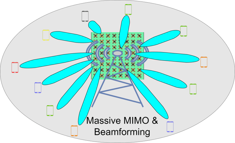
With 5G NR, there is possibility of having up to 256 transmit antenna at the BS side and that is where the term ‘massive MIMO’ comes into picture. Massive MIMO antennas uses a large number of antenna elements but operate at frequencies below 6 GHz. Essentially, they exploit many elements to realize a combination of BF and spatial multiplexing.
Beamforming (BF) Fundamentals
Beamforming is a well-known and established antenna technology. Cellular networks such as LTE apply this technology to improve overall performance. Objects are identified by radar applications using Beamforming. It has more importance in 5G cellular communications as it allows deployment of 5G in higher frequency ranges such as cm-wave and mm-wave frequency spectrum where it is necessary to achieve enough cell coverage i.e. to compensate for high path loss at these frequencies.
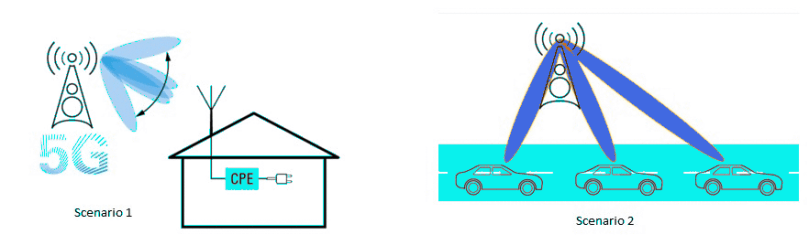
The ability to steer beams dynamically is equally important since blockage scenarios are likely to occur due to moving objects such as cars or even a human body which can block the line of sight path. Consider some examples below:
- In a fixed wireless access scenario, the customer premises equipment (CPE) in a household connects to an outdoor 5G BS. Here, no mobility is involved and a beam sweeping procedure would identify the best beam to be used.
- In contrast, Beamforming needs to be dynamic (steerable or switchable) when a moving car on a road is connected.
Support for BF is an essential capability in 5G NR which impacts the physical layer and higher layer resources. It is based on 2 fundamental physical resources: SS/PBCH blocks and the capability to configure channel state information reference signals (CSI-RS).
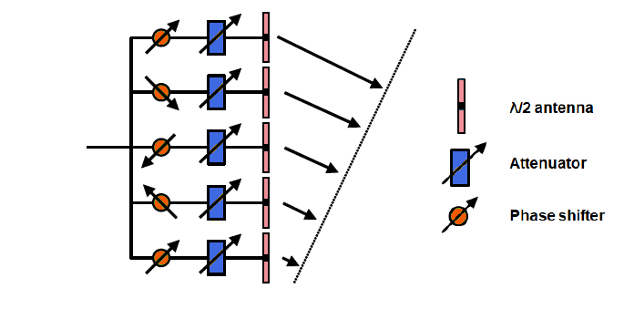
The principle of BF is to use the large number of antennas in, for example, an array. Each antenna can be controlled with a phase shifter and an attenuator. The antennas are usually half a wavelength of the signals they are optimized for. The phase of each antenna is then adjusted in order to control the direction of the beam. Preferably, the beam should be sent in the same direction as the UE transmitted in the UL. This means that the antennas and the logic controlling them must be able to measure the so called ‘angle of arrival’. If a signal comes from a direction in front of the antenna, all elements will receive a phase front of the signal at the same time. For Example: if the angle is 45 degrees, the antennas will receive the phase front of the signal with the time spread. By measuring the time delay between the arriving phase front to the antennas, it is possible to calculate the angle of arrival. To send the signal in the same direction, the phase front of the transmitted signal should be sent with the same time spread. Phase shifting can be done in the digital domain or analog domain.
Beamforming in 5G NR should be able to direct beams not only in horizontal direction but vertical direction as well, which is sometimes referred to as 3D MIMO as well. To be able to do that, antennas need to be put in a square, termed as Uniform Square Array (USA). Below is an example of 128 cross polarized antennas:
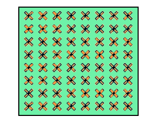
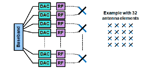
By having the possibility to pack antennas and radio equipment very tightly, it is now possible to create antenna solutions with integrated antennas, analog to digital converters and power amplifiers. The antennas are put in a USA with cross-polarized antennas with 32, 64 or 256 antennas. Behind the Digital-to-analog-converter (DAC) is the baseband part which creates and analyzes the signals in the digital form, which comprises of number of Digital signal processors (DSP) with high capacity.
As mentioned above, by measuring the phase front of the signal arriving to different antenna elements, it is possible to measure from which direction the signal comes in (Angle or arrival). To direct the radio energy in the same direction back to the UE, the same principle is used. This means that beams will be created from the antenna in different directions. By using different combinations of antennas, different beams can be created at the same time to different UEs located in different directions. However, the number of power amplifiers behind the antennas decide how many simultaneous beams can be created by the antenna. For Example: 8 beams can be created with 8 power amplifiers. The challenge is to pack amplifiers in an antenna and to reduce/remove the heat created by them as well as to limit the disturbance they cause to each other.
As a matrix is used, it is also possible to change the direction of the radio beam in both horizontal and vertical directions. In some case, it is referred to as 3D Beam Forming. This concept of creating beams from a Base Station will be a necessity in 5G NR when operating in very high frequency bands (FR2) due to bad radio propagation properties in these bands.
Similar principle can also be used on the receiver side in the UE or in the gNB receiver. The phase array can be set to amplify a signal arriving from a certain direction, which means that the receiver can focus on its antenna in a specific direction which is also referred to as Receiver side beam forming.
Operations in Beam Management
- Beam Measurement: UE provides measurement reports to the Base Station on a per beam basis.
- Beam Detection: UE identifies the best beam based on power measurements related to configured thresholds.
- Beam Recovery: UE is configured with basic information to recover a beam in case the connection is lost.
- Beam Sweeping: Using multiple beams at the Base Station to cover a geographic area and sweep through them at prespecified intervals.
- Beam Switching: UE switches between different beams to support mobility scenarios.
Types of Beamforming
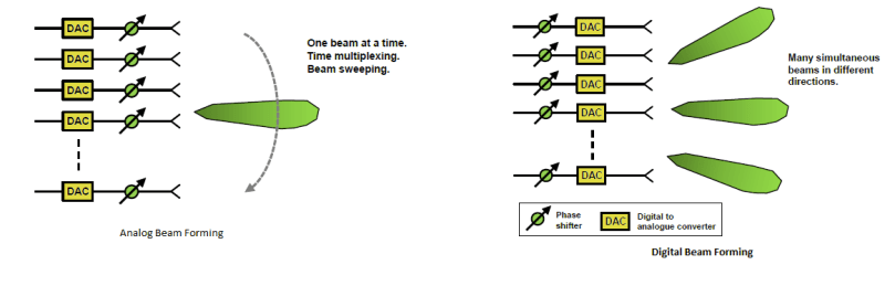
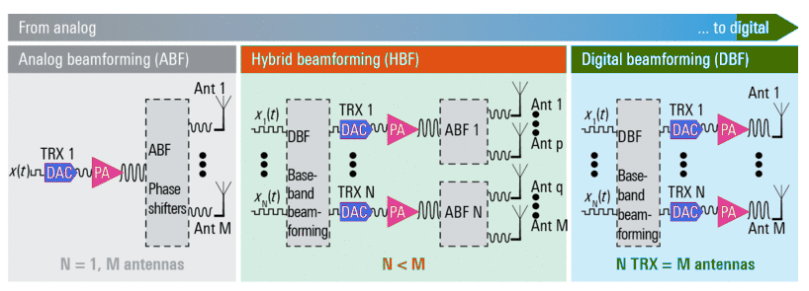
- Analog BF: In this implementation, the baseband signal is 1st modulated then amplified and then split among the available number of antennas. Each RF chain has the capability to change the amplitude and phase individually. Analog BF in the RF path is simple and uses a minimal amount of hardware, making it the most cost-effective way to build a BF array. The drawback is that system can only handle one data stream and generate one signal beam. The beams must be time multiplexed and beams pointing in different directions are separated in time.
- Digital BF: In this implementation, multiple digital streams are already generated in the baseband and as before, each is individually modified in phase and amplitude to generate the desired beam. So, several sets can be created and superimposed before feeding the array elements. This mechanism enables one antenna to generate multiple beams, each with its own signal and serving multiple users. Here, phase shifting is done before the Digital to Analog Conversion. BF modifications of the signals will be made in DSP by modifying the digital representation of the signal. This is the preferred method for lower frequencies in 5G as the advantage is that the phase and amplitude of each antenna can be controlled separately giving high flexibility. If each antenna can be controlled, full flexibility is possible with the number of beams the antenna can create at the same time. Here, phase shifting is done before the Digital to Analog Conversion. BF modifications of the signals will be made in DSP by modifying the digital representation of the signal. This is the preferred method for lower frequencies in 5G as the advantage is that the phase and amplitude of each antenna can be controlled separately giving high flexibility. If each antenna can be controlled, full flexibility is possible with the number of beams the antenna can create at the same time.
- Hybrid BF: This implementation combines both the above-mentioned methods. A limited number of digital streams feed multiple analog beamformers, whereas each is connected to a subset of total elements in the antenna array, which provides a compromise between implementation complexity, cost and flexibility.
Note: Digital BF seems to be the most obvious way to implement Spatial Multiplexing as same signal can be sent from all the antennas to a particular user, with possible variation in phase/amplitude per antenna or possible variation in phase/amplitude per subcarrier. This is particularly important for cases where there is no direct line of sight between the Base station and the user.
Evolution of Massive MIMO
It is generally acknowledged that network densification is one of the main solutions to the exploding demand for capacity. Densification, when defined as the number of antennas per unit area, can be achieved through multi‐antenna systems such as massive MIMO.
Network densification proposes the deployment of a large number of antennas per cell site, to form what is known as a ‘massive MIMO’ (multi‐user MIMO with very large antenna arrays) network, once the number of antennas exceeds the number of active UEs per cell. This emerging technology uses multiple co‐located antennas (up to a few hundred) to simultaneously serve / spatially multiplex several users in the same time‐frequency resource. As the aperture of the array grows with many antennas, the resolution of the array also increases. This effectively concentrates the transmitted power towards intended receivers, thus the transmit power can be made arbitrarily small, resulting in significant reductions in intra‐ and inter‐cell interference. Distributing antennas has also been shown to result in highest capacity.
The antennas used for the macro cells are 2×4 MIMO and those used for the small cells are 128×4 MIMO (i.e. Massive MIMO). According to DoCoMo, “the aim of using Massive MIMO is to bar jamming through the beamforming technology”.
Approach for Massive MIMO
The approach here is to base all the beams on the uplink channel estimation. Here, UE sends a pilot signal which will be a known signal and Base station estimates what it receives, and, on that basis, it estimates the channel for the users. Thus, Base station can find some well-matched estimates to the channel and there is no need to make assumptions from beginning as to how channel looks like. Base station can just measure what it sees. It is also scalable with many antennas. This approach is different from the conventional approach where different angular beams are tried and user reports the best one, which is not a very nice solution as there is possibility of a user to be at the boundary and it can cause too much inter-user interference.
If the number of applied antenna elements is significantly increased at the Base station, for example if 64 cross-polarized antennas are used, the network node becomes a massive MIMO BS. Even with the increased number of antenna elements, the number of spatial layers is not increased. 5G NR supports 8 layers on the DL and 4 layers on the UL. However, large number of antenna elements allows the combinations of beamforming with spatial multiplexing. So, Massive MIMO antennas enabled focused transmission and reception of signal energy in the smaller regions of space, which brings huge improvements in user throughput, capacity and energy efficiency, especially when combined with simultaneous scheduling of multiple users.
In the established sub-6 GHz frequency spectrum, Base Station apply a large number of TX/RX antenna elements to serve multiple users with parallel data streams with moderate antenna gains. In contrast, the high path loss attenuation in the cm-wave and mm-wave bands requires high antenna gains. Consequently, both the Base Station and UE antenna implementations focus on high gain and dynamic Beamforming algorithms i.e. all available TX elements are used to create a single beam.
Distributed MIMO
NR is ready to support distributed MIMO however the support was not complete in release 15. Distributed MIMO implies that the device can receive multiple independent physical data shared channels (PDSCHs) per slot to enable simultaneous data transmission from multiple transmission points to the same user which means that some MIMO layers are transmitted from one site while other layers are transmitted from another site.
Advantages of Massive MIMO
- With a greater number of antennas, beam width will be smaller (Narrower Beam due to involvement of fewer multipath components) leading to higher reliability and lower latency. This essentially means that the number of lost packets would be less and hence lesser retransmissions.
- Resource allocations are made simple in Massive MIMO. All subcarriers are good at all times. So, no need to schedule based on fading. Each user gets the whole bandwidth whenever needed.
- Massive MIMO can be very useful with:
- Mobile Broadband applications
- Very high spectral efficiency, multiplex many users
- Great improvements at the cell edge
- Ultra-Reliable Low Latency Communication (URLLC)
- Lesser lost packets, so Fewer retransmissions
- more predictable performance in the networks
- Massive Machine-Type Communication (mMTC)
- Can extend coverage, more cost-efficient deployment by putting up fewer Base Station in order to reach all the sensors.
- Can help reduce transmit power for battery powered devices
- Mobile Broadband applications
Limitations of Massive MIMO
- Works only with Time Division Duplex (TDD) mode where you change between UL and DL on the same frequency and for that reason, you can measure the channel in the UL and use it also for DL transmission.
- The performance of massive MIMO is limited by the finite and correlated scattering given the space constraints. The degrees of freedom of the system, solely determined by the spatial resolution of the antenna array, can reach saturation point. Also, in frequency division duplex (FDD) systems, channel estimation and feedback for a large number of antennas presents a challenge. Unless the channel structure is available at the BS, the prohibitive downlink channel training and feedback in FDD systems sets an upper limit on the number of BS antennas.
- With Massive MIMO, there is a challenge of manufacturing many low cost, low-precision components which also affects how to approach testing and verification of the performance of these antennas since over the air test methods must generally be applied.
Since this was just an introduction article, I might write another one in future to cover up more details about Massive MIMO.
References
- ‘Fundamentals of 5G Mobile Networks’ – Edited by Jonathan Rodriguez
- https://www.youtube.com/watch?v=qjqYRHYLoWo – A video tutorial explaining ‘Massive MIMO for 5G below 6 GHZ’
- https://www.youtube.com/watch?v=pE_FsnHtTxc – Beamforming (Massive MIMO)
- https://www.sharetechnote.com/html/Handbook_LTE_BeamForming.html
- https://pdfs.semanticscholar.org/9a2e/78fd79fd478f38200f803531fe3c82babc42.pdf
