

Introduction
Random Access (RACH) is the procedure where the User Equipment (UE) wants to create an initial connection with the network. This is one of the common procedures present in all the earlier versions of mobile systems including GSM, GPRS, UMTS and LTE, with some changes in messages exchanged between the UE and the Network. This procedure is done for many different reasons:
- UE wants to connect for outgoing call/data/sms
- UE responds to paging for incoming call/data/sms
- Request of other system information (SIB2 – SIB9)
- Handover to a new cell
- Need uplink synchronization (UE being idle from sometime and has not transferred data)
- Scheduling request when no UL resources are reserved for UE (no PUCCH)
- Beam Recovery
Like in LTE, it consists of 4 signals transmitted between the UE and the base station (gNB), shown below:

Summary of the procedure is: UE selects a “preamble” (a code sequence) and sends it at a random time on a UL channel called Physical Random Access Channel (PRACH). UE will start monitoring the DL channel to see if the base station (gNB) answers the request to connect to the network. If not, UE will make a new attempt with the increased power.
Random Access Response (RAR) sent by the network indicates which preamble it is related to, the Timing Advance (TA) it should use, a scheduling grant for sending Message 3 and a temporary Cell Radio Network Temporary Identifier (TC-RNTI). Message 3 and Message 4 will be used to resolve an eventual collision between 2 or more UEs attempting to access the network with the same preamble in the same physical PRACH resource, which is done by a unique identity (Either the RAN identity or the Core Network identity).
Once the random access (RA) procedure is completed, UE moves to connected state and UE-NW communication can continue using normal dedicated transmission.
Here in this blog, i will mostly focus on the RA Procedure during the standalone mode.
Characteristics of Preamble Transmission
In 5G NR, transmission timing of UL transmission is typically controlled by the network by means of regularly provided time adjustment commands (called closed-loop timing control). Prior to preamble transmission, there is no closed-loop timing control in operation so there will be an uncertainty in the preamble reception timing which for larger cells could be in order of 100µs or even more. So, in general, it is up to gNB scheduler to ensure that there are no other transmissions in the UL resources in which preamble transmission may take place. Below are some of the terms/characteristics associated with preamble transmission:
1. Guard Time
The distance to the base station is unknown, when the UE starts a RA procedure. But in a system using OFDM with strict timing of symbols, it is important that symbols from users arrive at the receiver approximately the same time. If not, the UL orthogonality gets lost within the cell. To handle this, PRACH must have a guard time so that the UEs far away in the cell can still send a preamble without disturbing another UEs UL transmission. The larger the cell is, the larger guard time should be. Below fig. shows the concept:
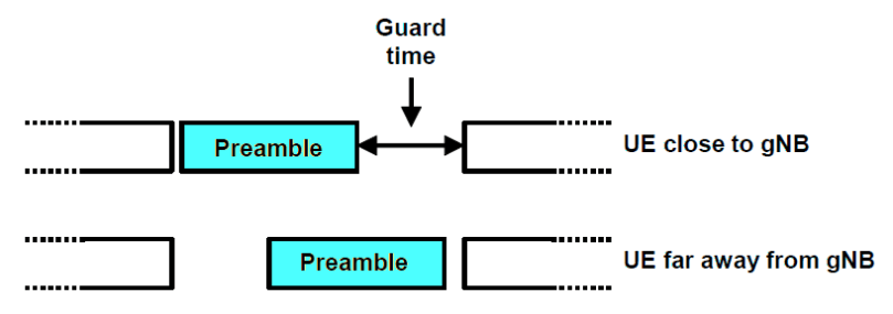
The guard time in 5G is not specified so it is up to the scheduler in the gNB to fix this by not scheduling other UEs for UL transmission.
Typically, normal UL transmissions are based on explicit scheduling grant, thereby enabling contention-free access while on the other hand, the initial random access is inherently contention based, which means that multiple UEs may initiate preamble transmission simultaneously. So, the preamble should be able to handle such kind of a situation and allow for correct preamble reception when such collisions occurs.
2. PRACH Resources
Preamble transmission can take place within a configurable subset of RACH slots that repeats itself every RACH configuration period, within a cell. Also, the amount of resources for the PRACH is configurable. If the cell is large, many UL requests will be made due to large number of users whereas for an isolated indoor cell, the amount of resources could be limited. The resource for PRACH is set in both time and frequency. Timing part indicates how often it is occurring in UL and the frequency part indicates how wide the resources are. RACH periodicity can be set between 10 and 160ms and this value indicates how often this pattern with resources is repeated (RACH Slot). Within each RACH Slot, there can be number of RACH occasions which specifies how many different resources there are for each slot.
Below is an example of PRACH Configuration:

3. Preambles
PRACH preamble is constructed by concatenating several short sequences, each sequence being of the same length as an OFDM symbol for other NR UL signals. These short sequences can be processed using the same FFT sizes as other UL signals thus avoiding the need of dedicated PRACH Hardware. This format also enables handling of large frequency offsets, fast time varying channels, phase noise and several receiver analog beamforming candidates within one PRACH preamble reception. Preamble format is also part of the cell random-access configuration i.e. each cell is limited to a single preamble format.
There are number of different preamble types available in the specification. The reason for having different alternatives is to provide flexibility regarding capacity, coverage and time delay (cell size). There are two main type of preambles:
- Long preamble for frequency range 1 (FR1)
- has 1.25 or 5KHz subcarrier spacing
- based on a sequence length L = 839
- 1.25KHz takes 6 resource blocks in frequency domain whereas 5Khz takes 24 resource blocks in frequency domain
- Intended to be used for macro deployments (Large Cells)
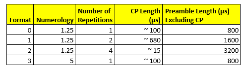
- Preamble formats for long preamble:
- Short preamble for both FR1 and FR2
- can have subcarrier spacings of 15, 30, 60 or 120KHz
- 15 kHz or 30 kHz in the case of operation below 6 GHz (FR1)
- 60 kHz or 120 kHz in the case of operation in the higher NR frequency bands (FR2).
- based on a sequence length L = 139
- takes 12 resource blocks regardless of subcarrier spacing
- Intended for small cells and indoor deployments
- Preamble formats for short preamble:
- can have subcarrier spacings of 15, 30, 60 or 120KHz
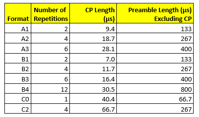
Note: The short preambles are, in general, shorter than the long preambles and often span only a few OFDM symbols. In most cases, it is possible to have multiple preamble transmissions multiplexed in time within a single RACH slot. In other words, for short preambles there may not only be multiple RACH occasions in the frequency domain but also in the time domain within a single RACH slot.
4. PRACH and Beam forming
The possibility to establish a suitable beam pair during the initial access phase itself and to apply the receiver side analog beam sweeping for the preamble reception is a key feature of 5G NR initial access and is different from LTE.
During the initial access to a cell, it is beneficial if the base station (gNB) knows which beam the UE is receiving as the strongest. This is done by connecting a specific instance of SSB (synchronization signal block) to a specific beam. The measurements are done on SSB, when the UE measures on several detectable beams. Each SSB has a parameter ‘time index’ which makes it unique. By connecting an SSB time index with a specific RACH resource (slot and/or preamble), the UE will use that when accessing the cell. The base station (gNB) then knows which beam the UE prefers.
Beam establishment during initial access is enabled by the possibility of associating different SSB time indices with different RACH time/frequency occasions and/or different preamble sequences. As different SSB time indices in practice correspond to SSB transmissions in different DL beams, this means that the network, based on the received preamble, should be able to determine the DL beam in which the corresponding UE is located. This beam can then be used as an initial beam for subsequent DL transmissions to the UE.
Furthermore, if the association between SSB time index and RACH occasion is such that a given time-domain RACH occasion corresponds to one specific SSB time index, the network will know when, in time, preamble transmission from UEs within a specific DL beam will take place. Assuming beam correspondence, the network can then focus the UL receiver beam in the corresponding direction for beam-formed preamble reception. This implies that the receiver beam will be swept over the coverage area synchronized with the corresponding DL beam sweep for the SS-block transmission.
Note: Beam-sweeping for preamble transmission is only relevant when analog beamforming is applied at the receiver side. If digital beamforming is applied, beam-formed preamble reception can be done from multiple directions simultaneously.
5. Preamble power control and Power Ramping
Generally, Preamble transmission takes place with a relatively large uncertainty in the required preamble transmit power. Therefore, Preamble transmission includes a power-ramping mechanism where the preamble may be repeatedly transmitted with a transmit power that is increased between each transmission. UE selects the initial preamble transmit power based on estimates of the DL path loss in combination with a target received preamble power configured by the NW. The path loss should be estimated based on the received power of the SSB that the UE has acquired and from which it has determined the RACH resource to use for the preamble transmission.
If no Random Access Response (RAR) is received within a predetermined window, the UE can assume that the preamble was not correctly received by the NW, and the reason might be that the preamble was transmitted with too low power. If this happens, the UE repeats the preamble transmission with the preamble transmit power increased by a certain configurable offset. This power ramping continues until a RAR has been received or until a configurable maximum number of retransmissions has been carried out, alternatively a configurable maximum preamble transmit power has been reached. In the two latter cases, the random-access attempt is declared as a failure.
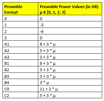
Below fig. shows the setting for each preamble format. Depending on the counter of transmission of preamble, the power is increased further as the current counter setting is multiplied by the signaled power ramping step, which can have values as 0 dB, 2 dB, 4 dB or 6 dB. The maximum number of preamble transmissions is also signaled to the UE and is equal to 3, 4, 5, 6, 7, 8, 10, 20, 50, 100 or 200 transmissions.
Type of Random Access procedures in 5G NR
Like LTE, 5G NR uses a contention based random access (CBRA) or contention free random access (CFRA) procedure.
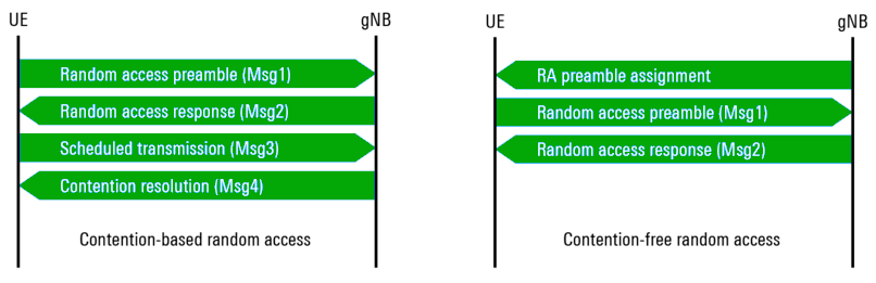
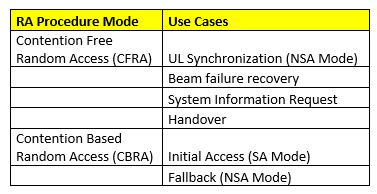
CFRA is the mode which UE initially uses to perform the RA procedure in Non standalone mode. UE uses an assigned preamble to perform RA and the procedure finishes once the UE receives RAR. CBRA is the fallback scenario in NSA mode. If CFRA fails e.g. if the transmission of the dedicated preamble is not acknowledged, within a configured time period, then UE may switch to CBRA to establish UL synchronization. CFRA is typically applied when the UE is already in CONNECTED mode. Below table provides an overview of different use cases for each procedure:
Fundamental difference between LTE and 5G NR regarding RA procedure is that the transmission of RA preamble for initial access is typically tied to the reception of the SSB in DL. In other words, UE preforms the signal quality measurements on the surrounding NR cells and decides the best received SSB (beam) index. The identified index determines on which frequency-time resource the RA preamble is transmitted using the PRACH. This enable gNB to focus its subsequent DL transmission of RAR in the same direction. For CFRA, the procedure ends with the reception of RAR. For CBRA, UE uses the information provided by the RAR to begin initial transmission on the PUSCH (message 3) using the same beam direction as for preamble transmission. Consequently, gNB sends the contention resolution using the same beam direction as for message 2.
Random Access procedure in Standalone Mode
In Non standalone mode, UE is signaled which RACH resource and preamble to use to perform Random Access procedure. For standalone mode, applying contention based random access (CBRA) the UE has to select a preamble and identify the frequency and time resources on the UL to transmit the preamble based on the results of signal quality measurements carried on the detected synchronization signal block (SSB).
Generation of random access preamble in based on the settings and values provided in RACH-Config-Common and RACH-ConfigGeneric, which also provides prach-ConfigurationIndex and thus the UE knows what preamble to use as well as in which subframe of a radio frame (SFN), it is allowed to transmit the preamble along with how many RACH occasions are applicable.
- So, when to transmit the RA preamble? – The answer comes from a generic parameter mentioned above prach-ConfigurationIndex present in RACH-ConfigGeneric, which informs UE not only about the preamble format to use but also the point in time in which to transmit the preamble in the UL. There are total of 256 indices (0 to 255) and the configuration of each index depends on the frequency range (FR1 or FR2) and for FR1, also the type of spectrum (paired or unpaired) utilized by the network. Refer to TS 38.211, section 6.3.3.2.
UE also uses the threshold (rsrp-ThresholdSSB) definition provided by RACH-ConfigCommon to identify the SSB it should consider for selecting the RA preamble.
As per TS 38.213, UE is provided with a number N of SSB blocks that are associated with 1 RACH occasion and a number R of contention-based preambles mapped to each SSB. These 2 numbers are provided to UE within RACH-ConfigCommon as ssb-perRACH-OccasionAndCB-PreamblesPerSSB. This is a 2-fold information element. First, it takes one of eight different values of N as N=1/8, ¼, ½, 1, 2, 4, 8 or 16. Consider a PRACH Configuration index as 133. This index defines 6 different RACH occasions. Let’s set N to 1/8, which means one SSB is associated with 8 consecutive RACH occasions. Furthermore, if msg1-FDM is set to 4, the 1st 2 RACH occasions are associated with the SSB with index #0. SSB Index #1 is associated with the following 2 RACH occasions (RO #2, RO #3).
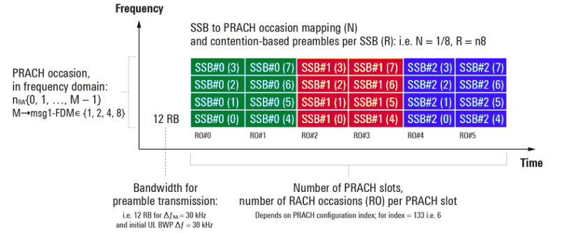
RACH occasions in the frequency – time domain and their association with SSBs
Depending on the value of N, there can be different values of R (see TS 38.331). The 1st 4 possible values of N (1/8, ¼, ½, 1) allow 16 different values of R with a standard step size of 4, starting at n4, n8… etc. If N=2, R can assume one of the 8 different values with n4, n8…n32. If N is 4,8 or 16, the values of R are either in the range from 1 to 16, 1 to 8 or 1 to 4 respectively. For R=n8 means 8 preambles out of a total of 64 are associated with 1 SSB, starting with index 0. In other words, preambles 0 to 7 are associated with SSB index #0, preambles 8 to 15 are associated with SSB index #1 and so forth.
Random Access Response (RAR) Reception by UE
Network will acknowledge the reception of RA preamble by transmitting MSG2, which is Random Access Response (RAR) on the DL to the UE. RAR is transmitted as a conventional DL PDCCH/PDSCH transmission with the corresponding PDCCH transmitted within the common search space. The information on the configuration of the control channel PDCCH is provided as part of ServingCellConfigCommonSIB in SIB1 and thus the UE knows which frequency and time resources to monitor for PDCCH carrying a DCI format 1-0 for which CRC is scrambled with RA-RNTI. DCI provides the frequency and time resource information on which RAR is carried by Resource block.
Assuming the NW is able to accommodate the UE based on its previously sent preamble, it would send a Random Access Preamble Id (RAPID) along with associated RAR. The UE compares received RAPID with the sequence it had selected as the preamble. If both matches, the reception of RAR is considered successful. Following the RAPID is the RAR which provides the UE with several pieces of information mentioned below:
- Information about the RA preamble sequence the network detected and for which the response is valid;
- Timing correction calculated by the network based on the preamble receive timing;
- Scheduling grant, indicating resources that UE will use for the transmission of the subsequent Message 3
- A temporary identity, the TC-RNTI, used for further communication between UE and network. The identity is 16 bit long and can be in the range of 0001 to FFEF (hex).
If the network detects multiple RA attempts (from different UEs), the individual response messages can be combined in a single transmission. Therefore, the response message is scheduled on the DL-SCH and indicated on a PDCCH using an identity reserved for RAR, the RA-RNTI. The use of the RA-RNTI is also necessary as a UE may not have a unique identity in the form of an allocated C-RNTI.
If the UEs that performed RA in the same resource used different preambles, no collision will occur and from the DL signaling it is clear to which UE(s) the information is related. However, there is a certain probability of contention—that is, multiple UEs using the same RA preamble at the same time. In that case, multiple UEs will react upon the same DL response message leading to collision.
Upon reception of the RAR, the UE will adjust its UL transmission timing and continue to the third step. If CFRA using a dedicated preamble is used, then this is the last step of the RA procedure as there is no need to handle contention in this case. Moreover, the UE already has a unique identity allocated in the form of a C-RNTI.
In the case of DL beamforming, the RAR should follow the beamforming used for the SS block which was acquired during the initial cell search. This is important as the UE may use receive-side beamforming and it needs to know how to direct the receiver beam. By transmitting the RAR using the same beam as the SS block, the UE knows that it can use the same receiver beam as identified during the cell search.
Message 3 Transmission
After the 2nd step, the UE is time synchronized in the UL direction. However, before user data can be transmitted to/from the UE, a unique identity within the cell, the C-RNTI, must be assigned to the UE (unless the UE already has a C-RNTI assigned). Depending on the UE state, there may also be a need for additional message exchange for setting up the connection.
So, in the next step, the UE transmits the necessary messages to the gNB using the UL-SCH resources assigned in the RAR in the previous step. An important part of the UL message is the inclusion of a UE identity, as this identity is used as part of the contention-resolution mechanism in the 4th step. If the UE is already known by the radio-access network, that is, in RRC_CONNECTED or RRC_INACTIVE state, the already-assigned C-RNTI is used as the UE identity (The UE identity is included as a MAC control element on the UL-SCH). Otherwise, a core-network UE identifier is used and the gNB needs to involve the core network prior to responding to the UL message in step 4.
Contention Resolution with Connection Set Up (Message 4)
The last step in the RA procedure consists of a DL message for contention resolution. Note that, from the 2nd step, multiple UEs performing simultaneous RA attempts using the same preamble sequence in the 1st step, listen to the same response message in the 2nd step and therefore have the same temporary identifier. Hence, the 4th step in the RA procedure is a contention-resolution step to ensure that a UE does not incorrectly use another UE’s identity.
The contention resolution mechanism differs somewhat depending on whether the UE already has a valid identity in the form of a C-RNTI or not. Note that the network knows from the UL message received in step 3 whether the UE has a valid C-RNTI or not. If the UE already had a C-RNTI assigned, contention resolution is handled by addressing the UE on the PDCCH using the C-RNTI. Upon detection of its C-RNTI on the PDCCH, the UE will declare the RA attempt successful and there is no need for contention-resolution-related information on the DL-SCH. Since the C-RNTI is unique to one UE, unintended UEs will ignore this PDCCH transmission.
If the UE does not have a valid C-RNTI, the contention resolution message is addressed using the TC-RNTI and the associated DL-SCH contains the contention-resolution message. Upon reception of Message 3, the MAC layer at the UE starts the ra-ContentionResolutionTimer. The value of contention resolution timer is provided with RACH-ConfigCommon. After starting the timer, UE begins monitoring the PDCCH for DCI format 1_0 with the CRC scrambled with corresponding TC-RNTI. Upon reception of the PDSCH, timer is stopped. If the decoded MAC PDU contains a Contention Resolution Identity (48 bits) that matches the CCCH SDU transmitted in Message 3, the contention resolution is considered successful. Furthermore, the C-RNTI is set to the previously temporary identity (TC-RNTI) and RA procedure is considered to be executed successfully. In response to PDSCH reception, UE transmits an HARQ-ACK on the PUCCH. The PUCCH transmission is on the same initial bandwidth part as the Message 3 PUSCH transmission.
UEs that do not detect PDCCH transmission with their C-RNTI or do not find a match between the identity received in the 4th step and the respective identity transmitted as part of the 3rd step are considered to have failed the RA procedure and need to restart the procedure from the 1st step. No HARQ feedback is transmitted from these UEs. Moreover, a UE that has not received the DL message in step 4 within a certain time from the transmission of the UL message in step 3 will declare the RA procedure as failed and need to restart from the 1st step.
References:
- https://www.etsi.org/deliver/etsi_ts/138200_138299/138211/15.08.00_60/ts_138211v150800p.pdf
- https://www.etsi.org/deliver/etsi_ts/138200_138299/138213/15.09.00_60/ts_138213v150900p.pdf
- https://www.etsi.org/deliver/etsi_ts/138300_138399/138331/15.09.00_60/ts_138331v150900p.pdf
- www.sharetechnote.com
- “5G NR – The next generation wireless access technology” – By Erik Dahlman, Stefan Parkvall, Johan Sköld
