Introduction
Carrier Aggregation is a technology that aggregates multiple component carriers (CC), which can be jointly used for transmission to/from a single device. It combines two or more carriers into one data channel to enhance the data capacity of a network. Using existing spectrum, Carrier Aggregation helps mobile network operators (MNOs) in providing increased UL and DL data rates. When Carrier Aggregation is deployed, frame timing and SFN are aligned across cells that can be aggregated. 5G NR utilizes CA in both FR1 and FR2, supporting up to 16 component carriers. For Release 15, the maximum number of configured Component Carriers for a UE is 16 for DL and 16 for UL.
Important characteristics:
- Up to 16 carriers (contiguous and non-contiguous) can be aggregated
- Carriers can use different numerologies
- Transport block mapping is per carrier
- Cross carrier scheduling and joint feedback are also supported
- Flexibility for network operators to deploy their licensed spectrum by using any of the CA types (such as intra-band contiguous, intra-band noncontiguous or inter-band noncontiguous)
History
LTE release 10 introduced enhanced LTE spectrum flexibility through carrier aggregation which was required to support higher bandwidths and fragmented spectra. Up to 5 component carriers, possibly each of different bandwidth, can be aggregated in this release, allowing for transmission bandwidths of up to 100MHz. All component carriers need to have the same duplex scheme and in the case of TDD, same uplink downlink configuration.
In LTE release 10, Backwards compatibility was ensured as each component carrier uses the release-8 structure. Hence, to a release-8/9 device each component carrier will appear as an LTE release-8 carrier, while a carrier-aggregation capable device can exploit the total aggregated bandwidth, enabling higher data rates. In the general case, a different number of component carriers can be aggregated for the downlink and uplink. This was an important property from a device complexity point of view where aggregation can be supported in the downlink where very high data rates are needed without increasing the uplink complexity.
Release 13 marked the start of LTE Advanced Pro, included various enhancements in Carrier Aggregation. The number of component carriers possible to aggregate was increased to 32, resulting in a total bandwidth of 640MHz and a theoretical peak data rate around 25 Gbit/s in the DL considering 8 layers spatial multiplexing and 256 QAM. The main motivation for increasing the number of subcarriers was to allow for very large bandwidths in unlicensed spectra.
LTE release 13 also introduced license-assisted access, where the carrier aggregation framework is used to aggregate downlink carriers in unlicensed frequency bands, primarily in the 5 GHz range, with carriers in licensed frequency bands. Mobility, critical control signaling and services demanding high quality-of-service rely on carriers in the licensed spectra while (parts of) less demanding traffic can be handled by the carriers using unlicensed spectra.
In LTE release 14, license-assisted access was enhanced to address uplink transmissions also.
Carrier aggregation was one of the most successful enhancements of LTE till now with new combinations of frequency band added in every release.
Carrier Aggregation in NR
Like LTE, multiple NR carriers can be aggregated and transmitted in parallel to/from the same device, thereby allowing for an overall wider bandwidth and correspondingly higher per-link data rates. The carriers do not have to be contiguous in the frequency domain but can be dispersed, both in the same frequency band as well as in different frequency bands, resulting in three difference scenarios:
• Intraband aggregation with frequency-contiguous component carriers;
• Intraband aggregation with non-contiguous component carriers;
• Interband aggregation with non-contiguous component carriers.
Below figure depicts these 3 scenarios:
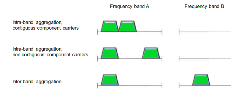
Although the overall structure is the same for all three cases, the RF complexity can be vastly different.
Up to 16 carriers, having different bandwidths and different duplex schemes, can be aggregated allowing for overall transmission bandwidths of up to 6,400 MHz (16 x 400 MHz) = 6.4 GHz, which is more than typical spectrum allocations.
A device capable of CA may receive or transmit simultaneously on multiple component carriers while a device not capable of CA can access one of the component carriers. It is worth noting that in the case of Inter-band carrier aggregation of multiple half-duplex (TDD) carriers, the transmission direction on different carriers does not necessarily have to be the same. This implies that a carrier-aggregation-capable TDD device may need a duplex filter, unlike the typical scenario for a noncarrier-aggregation-capable device.
In the specifications, carrier aggregation is described using the term cell, that is, a carrier-aggregation-capable device can receive and transmit from/to multiple cells. One of these cells is referred to as the primary cell (PCell). This is the cell which the device initially finds and connects to, after which one or more secondary cells (SCells) can be configured, once the device is in connected mode. The secondary cells can be rapidly activated or deceived to meet the variations in the traffic pattern. Different devices may have different cells as their primary cell—that is, the configuration of the primary cell is device-specific. Furthermore, the number of carriers (or cells) does not have to be the same in UL and DL. In fact, a typical case is to have more carriers aggregated in the DL than in the UL. Reasons being:
- There is typically more traffic in the DL that in the UL.
- The RF complexity from multiple simultaneously active uplink carriers is typically larger than the corresponding complexity in the downlink.
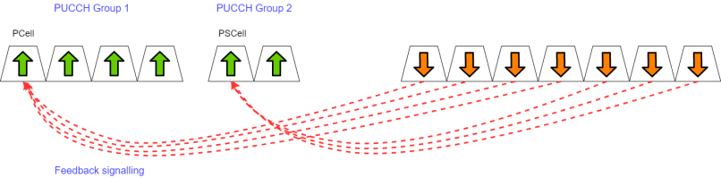
Carrier aggregation uses L1/L2 control signaling for the same reason as when operating with a single carrier. As baseline, all the feedback is transmitted on the primary cell, motivated by the need to support asymmetric carrier aggregation with the number of downlink carriers supported by a device different than the number of uplink carriers. For many downlink component carriers, a single uplink carrier may carry a large number of acknowledgments. To avoid overloading a single carrier, it is possible to configure two PUCCH groups where feedback relating to the first group is transmitted in the uplink of the PCell and feedback relating to the other group of carriers is transmitted on the primary second cell (PSCell).
If carrier aggregation is used, the device may receive and transmit on multiple carriers, but reception on multiple carriers is typically only needed for the highest data rates. It is therefore beneficial to inactivate reception of carriers not used while keeping the configuration intact. Activation and inactivation of component carriers can be done through MAC signaling containing a bitmap where each bit indicates whether a configured SCell should be activated or deactivated.
Difference between self-scheduling and cross-carrier scheduling
Scheduling grants and scheduling assignments can be transmitted on either the same cell as the corresponding data, known as self-scheduling, or on a different cell than the corresponding data, known as cross-carrier scheduling.

Let’s discuss in detail – the scheduling decisions are taken per carrier and the scheduling assignments are transmitted separately for each carrier, that is, a device scheduled to receive data from multiple carriers simultaneously receives multiple PDCCHs. A PDCCH received can either point to the same carrier, known as self-scheduling, or to another carrier, commonly referred to as cross-carrier scheduling or cross-scheduling. In case of cross-carrier scheduling of a carrier with a different numerology than the one upon which the PDCCH was transmitted, timing offsets in the scheduling assignment, for example, which slot the assignment relates to, are interpreted in the PDSCH numerology (and not the PDCCH numerology).
Carrier Aggregation support in MAC Layer
MAC Layer is responsible for multiplexing/demultiplexing data across multiple component carriers when carrier aggregation is used. In case of CA, it is responsible for distributing data from each flow across the different component carriers, or cells.
The basic principle for carrier aggregation is independent processing of the component carriers in the physical layer, including control signaling, scheduling and HARQ retransmissions, while carrier aggregation is invisible above the MAC layer. Carrier aggregation is therefore mainly seen in the MAC layer, where logical channels, including any MAC control elements, are multiplexed to form transport blocks per component carrier with each component carrier having its own HARQ entity.
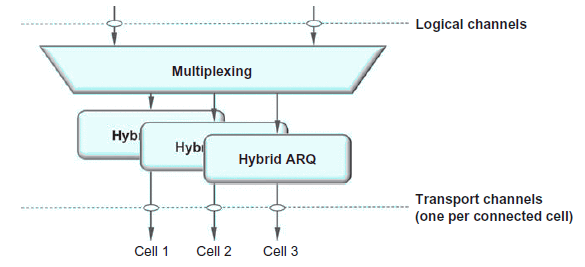
Note: In the case of carrier aggregation, there is one DL-SCH (or UL-SCH) per component carrier seen by the device
Relation with Dual Connectivity
Dual connectivity implies that a device is simultaneously connected to two cells. User-plane aggregation, where the device is receiving data transmission from multiple sites, separation of control and user planes, and uplink-downlink separation where downlink transmissions originate from a different node than the uplink reception node are some examples of the benefits with dual connectivity. To some extent it can be seen as carrier aggregation extended to the case of non-ideal backhaul. It is also essential for NR when operating in non-standalone mode with LTE providing mobility and initial access.
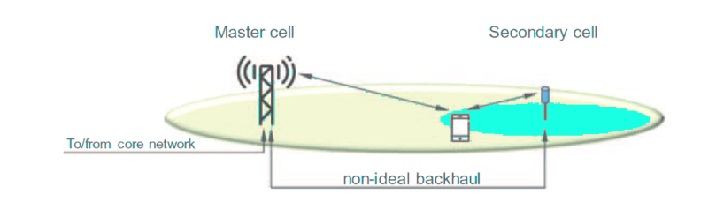
In dual connectivity, a device is connected to two cells, or in general, two cell groups, the Master Cell Group (MCG) and the Secondary Cell Group (SCG). The reason for the term cell group is to cover also the case of carrier aggregation where there are multiple cells, one per aggregated carriers, in each cell group. The two cell groups can be handled by different gNBs.
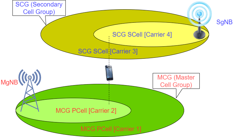
A radio bearer is typically handled by one of the cell groups, but there is also the possibility for split bearers, in which case one radio bearer is handled by both cell groups. In this case, PDCP is in charge of distributing the data between the MCG and the SCG and thus PDCP plays an important role for Dual connectivity support.
Differences between Dual Connectivity and Carrier Aggregation
Both carrier aggregation and dual connectivity result in the device being connected to more than one cell. Despite this similarity, there are fundamental differences, primarily related to how tightly the different cells are coordinated and whether they reside in the same or in different gNBs.
Carrier aggregation implies very tight coordination, with all the cells belonging to the same gNB. Scheduling decisions are taken jointly for all the cells the device is connected to by one joint scheduler. Dual connectivity, on the other hand, allows for a much looser coordination between the cells. The cells can belong to different gNBs, and they may even belong to different radio-access technologies as is the case for NR-LTE dual connectivity in case of non-standalone operation.
Carrier aggregation and dual connectivity can also be combined. This is the reason for the terms master cell group and secondary cell group. Within each of the cell groups, carrier aggregation can be used.
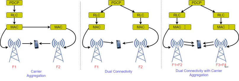
Multi Connectivity includes Dual Connectivity (PDCP UP Split) and Carrier Aggregation (MAC UP Split) as shown in the figure below:
Dual Connectivity should be preferred when latency is not neglectable between paths i.e. > 5-10ms or when there is a different RAT to be connected and TN of the master side is congested, whereas Carrier Aggregation has better and faster utilization of radio resources than Dual Connectivity but is used to connect same RATs. It requires low inter site latency (<5ms).
Note:
- In the case of carrier aggregation or dual connectivity, multiple power headroom reports can be contained in a single message (MAC control element).
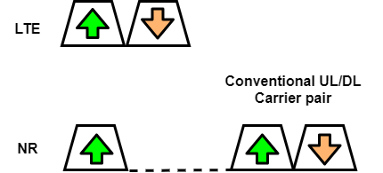
- NR does not support carrier aggregation with LTE and thus dual connectivity is needed to support aggregation of the LTE and NR throughput.
- NR specifications supports carrier aggregation, where multiple carriers are present within a band, or in multiple bands, can be combined to create larger transmission bandwidths.
Relation with Supplementary Uplink
Both these techniques allow the uplink transmission to be switched between the FDD-band and the 3.5 GHz band. The use of these mechanisms effectively utilizes idle sub-3 GHz band resources, improve the uplink coverage of C-band, and enable the provisioning of 5G services in a wider area. Both solutions, NR Carrier Aggregation and Supplementary Uplink, offer transport of UL user data using sub-3GHz band NR radio resources. NR CA provides the added benefit of also providing sub-3GHz DL user data support on the FDD-band downlink, using 3GPP specified LTE-NR spectrum sharing, if needed. This provides opportunity to aggregate NR bandwidth as well as better operation of the NR uplink.
Difference between Carrier Aggregation (CA) and supplementary uplink (SUL)
Supplementary uplink differs from the aggregated uplink in that the UE may be scheduled to transmit either on the supplementary uplink or on the uplink of the carrier being supplemented, but not on both at the same time.
In a typical carrier aggregation scenario:
- Main aim of carrier aggregation is to enable higher peak data rates by increasing the bandwidth available for transmission to/from a device.
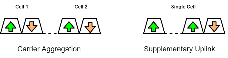
- The two (or more) carriers are often of similar bandwidth and operating at similar carrier frequencies, making aggregation of the throughput of the two carriers more beneficial. Each uplink carrier is operating with its own associated downlink carrier, simplifying the support for simultaneous scheduling of multiple uplink transmissions in parallel. Formally, each such downlink carrier corresponds to a cell of its own and thus different uplink carriers in a carrier-aggregation scenario correspond to different cells.
While in case of SUL scenario:
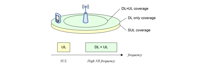
- Main aim of SUL is to extend uplink coverage, that is, to provide higher uplink data rates in power-limited situations, by utilizing the lower path loss at lower frequencies
- The supplementary uplink carrier does not have an associated downlink carrier of its own. Rather, the supplementary carrier and the conventional uplink carrier share the same downlink carrier. Consequently, the supplementary uplink carrier does not correspond to a cell of its own. Instead, in the SUL scenario there is a single cell with one downlink carrier and two uplink carriers.
Benefits of Carrier Aggregation
- Better Network Performance: Carriers provide a more reliable and stronger service with less strain on individual networks.
- Leveraging of underutilized spectrum: CA enables carriers to take advantage of underutilized and unlicensed spectrum, thereby extending the benefits of 5G NR to these bands.
- Increased uplink and downlink data rates: Wider bandwidth mean higher data rates.
- More efficient use of spectrum: Operators can combine fragmented smaller spectrum holdings into larger and more useful blocks and can create aggregated bandwidths greater than those that would be possible from a single component carrier.
- Network carrier load balancing: Enables intelligent and dynamic load balancing with real‐time network load data.
- Higher capacity: CA doubles the data rate for users while reducing latency with a good amount.
- Scalability: Expanded coverage allows carriers to scale their networks rapidly.
- Dynamic switching: CA enables dynamic flow switching across component carriers (CCs).
- Better user experience: CA delivers a better user experience with higher peak data rates (particularly at cell edges), higher user data rates, and lower latency, as well as more capacity for “bursty” usage such as web browsing and streaming video.
- Enabling of new mobile services: Delivering a better user experience opens opportunities for carriers to innovate and offer new high bandwidth/high data rate mobile services.
- Can be combined with Dual Connectivity
Disadvantages/Challenges with Carrier Aggregation:
- Intra‐band uplink CA signals use more bandwidth and have higher peak‐to‐average power ratios (PAPRs)
- Many possible configurations of resource blocks (RBs) exist in multiple component carriers (CCs) where signals could mix and create spurious out‐of‐band problems.
- Intra‐band CA signals present mobile device designers with many challenges because they can have higher peaks, more signal bandwidth, and new RB configurations. A Power Amplifier design must be tuned for very high linearity even though the signal power may be backed off. Adjacent channel leakage, intermodulation products of non‐contiguous RBs, spurious emissions, noise, and sensitivity must be considered. The tradeoff of linearity comes at the expense of efficiency and thermal effects.
- Inter‐band CA combines transmit signals from different bands. The maximum total power transmitted from a mobile device is not increased in these cases, so for two transmit bands, each band carries half the power of a normal transmission, or 3 dB less than a non‐CA signal. Because different PAs are used to amplify the signals in different bands, and the transmit power is reduced for each, the PA linearity isn’t an issue. Other front‐end components, like switches, have to deal with high‐level signals from different bands that can mix and create intermodulation products. These new signals can interfere with one of the active cellular receivers or even another receiver on the phone, like the GPS receiver. To manage these signals, switches must have very high linearity.
References:
- https://www.gsma.com/futurenetworks/wp-content/uploads/2019/03/5G-Implementation-Guideline-v2.0-July-2019.pdf
- “5G NR – The next generation wireless access technology” – By Erik Dahlman, Stefan Parkvall, Johan Sköld
- https://www.3gpp.org/technologies/keywords-acronyms/101-carrier-aggregation-explained
- https://www.qorvo.com/design-hub/ebooks/5g-rf-for-dummies